3-PHASE STEPPING DRIVER CF3065D
Overview
CF3065D uses servo control principle technology. It has motor parameter adaptive function which ensures the best performance of the motor. The technology can significantly reduce the motor noise and improve stability. The maximum drive current is 5.8A and the highest positioning accuracy of 64 subdivisions can reach up to 12,800 steps / turn.
Main Application Fields
The motor drive is applicable for all kinds of motion control automation equipment and instruments, such as electronic processing and testing, semiconductor packaging, laser cutting and welding, laser phototypesetting, packaging machinery, engraving machine, marking machine, cutting machine, garment plotter, CNC machine tools Embroidery machine, packaging machinery. It is the first choice for users who expect low noise, high-speed performance and cost-effective fields.
Drive Function Description
Drive function | Operating Instructions |
Micro-step subdivision setting | The SW5-SW8 four DIP switches are used to set the drive¡¯s micro-step subdivisions among its total 15 levels. When setting the subdivision, the drive should be stopped running first. For specific settings, please refer the drive panel instructions. |
Output current setting | The SW1-SW3 three DIP switches are used to set the drive¡¯s output current, which has total 8 levels. For specific settings, please refer the drive panel instructions. |
Automatic half-current function | Users can set the automatic half-current function of the drive via SW4. OFF indicates that the quiescent current is set to half the dynamic current, ON indicates that the quiescent current is the same as the dynamic current. SW4 should be set to OFF in general use, so that the heat of the motor and the drive can be reduced and the reliability is improved. Approximately 0.4 seconds after the pulse train is stopped, the current is automatically reduced to about half (60% of the actual value), and the calorific value is theoretically reduced by 36%. |
Signal interface | PUL+ and PUL- are the positive and negative terminals of the control pulse signal. DIR+ and DIR- are the positive and negative terminals of the direction signal. ENA+ and ENA- are the positive and negative terminals of the enable signal. |
Motor interface | U, V, W corresponds to the motor¡¯s winding wire U, V, W. Switching any two pairs of three winding wires can change the motor¡¯s direction. |
Power interface | Use DC power supply. The working voltage range is recommended between 20-50VDC, power supply should be greater than 200W. The proposed working voltage is 36VDC. |
Indicator lights | The drive has red and green 2 indicators. The green light is the power indicator, which keeps on when the drive is powered on. The red light is the fault indicator, which keeps on when there is overvoltage or overcurrent fault. The red light will be off after the fault is cleared. When the drive fails, do power cycle and reboot to clear the fault. |
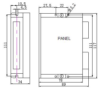
Installation Notes | The dimensions of the drive are 117 * 78 * 34mm and the mounting pitch is 111mm. It can be installed in either horizontal or vertical orientation. The vertical is recommended. When installing, make it close to the metal cabinet to facilitate heat dissipation. |
Installation Dimensions Diagram


